
This engineering guide explains what a 1000 LPH RO system delivers, who it is for, and how to specify recovery, pretreatment, power and footprint. You will also find P&ID/BOM highlights, a commissioning checklist, operations & CIP routines, and RFQ-ready forms to secure a fast, accurate quote.
Ready to proceed? View the product page: 1000 LPH Reverse Osmosis System. See related categories: Water Treatment Packages · RO Membranes (4040/8040).
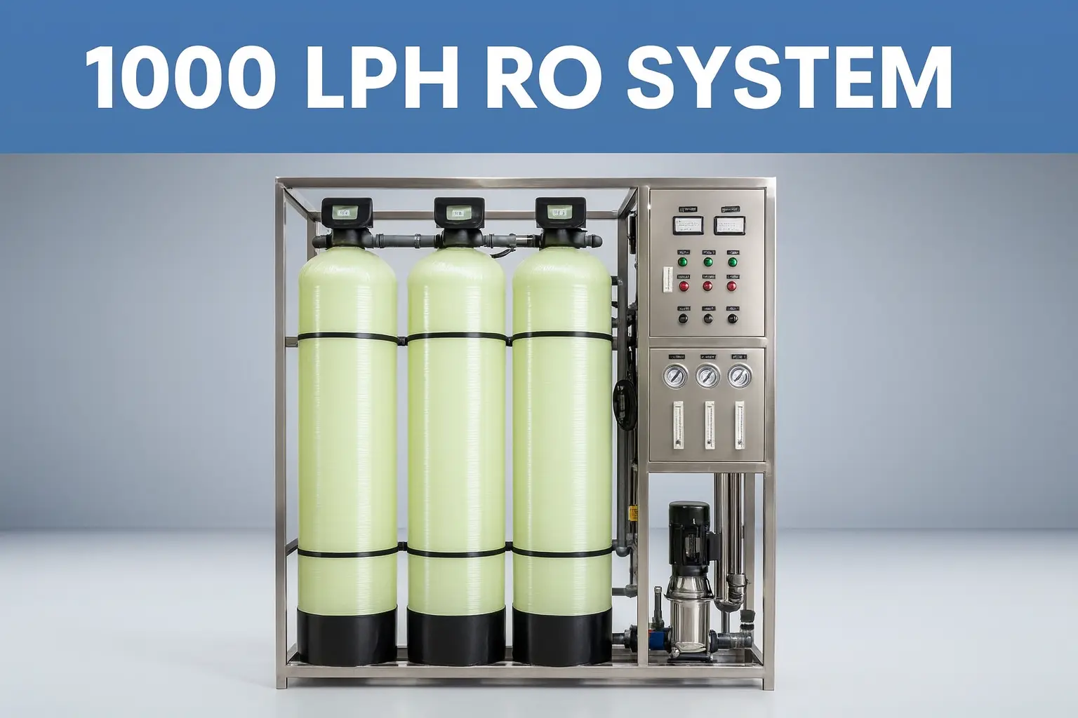
1) Executive Summary (TL;DR)
- Designed flow: 1000 LPH permeate at 25 °C with brackish feed water (typically 500–2,000 ppm TDS).
- Typical configuration: 2×4040 BWRO membranes, 2×1 pressure vessels, HP pump ~2.2–3 kW, 5 µm cartridge filter, PLC-based control, online conductivity, pressure and flow.
- Recommended recovery: 50–70% depending on feed TDS and chemistry; see the table below to pick your starting point.
- Common options: activated carbon, softener or UF, antiscalant dosing, UV/EDI, permeate tank and distribution loop.
For fast sizing, download the Spec Pack (P&ID + BOQ) from the product page: 1000 LPH RO.
2) Who Is It For & Typical Use Cases
- Beverage & food: ingredient/blend water, boiler feed makeup.
- Pharma pre-treatment: PW/HPW upstream of storage tanks and loops.
- Electronics/general manufacturing: rinse/process water at stable conductivity.
- Facilities/utilities: small industrial plants requiring 1 m³/h continuous permeate.
Pair the system with a permeate buffer tank for stable operations: Aseptic stainless steel water tanks.
3) 1000 LPH RO System Specs at a Glance
| Item | Typical Value / Range | الملاحظات |
|---|---|---|
| Permeate flow | 1000 LPH @ 25 °C | Correct for temperature with TCF (↓ flow at low temp) |
| Feed TDS | 500–2,000 ppm (brackish) | Higher TDS → lower recovery / higher pressure |
| التعافي | 50–70% | See Recovery vs TDS table |
| Permeate conductivity | ~10–50 µS/cm | Depends on feed and design recovery |
| Salt rejection | >98% NaCl (typical for BWRO) | Brand/model dependent |
| Membranes | 2×4040 BWRO | Vessels: 2×1 |
| مضخة الضغط العالي | ~2.2–3 kW | Power at nominal conditions |
| المعالجة المسبقة | 5 µm cartridge, antiscalant/softener/UF | Choose per water chemistry |
| Power | 380–415 V, 50–60 Hz | 3-phase (site standard) |
| Frame / footprint | SS304; ~1.2×0.8 m | Height ~1.6 m (indicative) |
| Instrumentation | Pressure, flow, conductivity | PLC/HMI with alarms |
| Options | UV/EDI/double-pass RO | See upgrades section |

4) Recovery vs Feed TDS (Start Here)
Pick an initial recovery and design pressure from the table below. Verify with your membrane supplier’s software using real water analysis (TDS, hardness, alkalinity, silica, iron/manganese, temperature).
| Feed TDS (ppm) | Recommended Recovery | Design Pressure (bar) | الملاحظات |
|---|---|---|---|
| ~500 | 65–70% | 8–10 | Antiscalant usually sufficient; monitor SDI |
| ~1,000 | 60–65% | 10–12 | Consider softener if hardness is high |
| ~1,500 | 55–60% | 12–14 | Antiscalant + careful recovery control |
| ~2,000 | 50–55% | 14–16 | Higher scaling risk; check silica/alkalinity |

5) Pretreatment & Water Chemistry
- SDI < 5 at the RO inlet; backwashable filtration or UF upstream if colloids are persistent.
- Free chlorine < 0.1 ppm (use activated carbon or sodium metabisulfite as appropriate).
- Hardness/alkalinity/silica: choose between softener vs antiscalant based on water analysis.
- Iron/manganese: remove to trace levels to avoid fouling and membrane oxidation risks.
Choose BWRO elements from our membrane category: RO membranes (4040/8040) — e.g. ULP31-4040.
6) 1000 LPH RO system Sizing & Selection Workflow
- Define target conductivity and operating hours; add a permeate buffer tank if the draw is intermittent.
- Correct for temperature via TCF. Lower temperatures reduce flux—consider margin in winter.
- Select elements (4040 BWRO) and calculate flux: Permeate ≈ Σ(Area × flux × TCF). Keep transmembrane pressure within envelope.
- Pick recovery from the table above; validate with scaling indices and supplier software.
- Choose Configuration:
- Config A (lower CAPEX): 2×4040, antiscalant dosing, recovery 55–65%.
- Config B (higher recovery): 2×4040 + optimized antiscalant program, recovery up to ~70% at low TDS.
7) Electrical, Piping & Utilities
- Power: 380–415 V, 50–60 Hz, ~2.2–3 kW HP pump; allow for start current per motor spec.
- الوصلات: feed, permeate, concentrate, CIP ports; provide suitable drain for flushing/CIP.
- Footprint: ~1.2×0.8 m frame, ~1.6 m height; ensure handling/clearance and noise considerations.
- Permeate tank: size for buffer; include venting and level control. See aseptic tank options.
8) P&ID and Bill of Materials (BOM)
Core components: HP pump, 4040 elements & vessels, 5 µm cartridge housing, pressure gauges/transmitters, flow meters, conductivity sensors, valves & control cabinet (PLC/HMI).

Get the Spec Pack (PDF + P&ID + BOQ) via the product page: 1000 LPH RO System.
9) Commissioning & Acceptance (How-To)
| Step | What to check | Pass criteria |
|---|---|---|
| Pre-start | Wiring/rotations, leaks, valve positions, SDI & residual chlorine | SDI <5; Cl₂ <0.1 ppm |
| Flush | Initial rinse to drain until stable conductivity | Conductivity trend stable |
| Set recovery | Adjust concentrate valve/backpressure | Within target (e.g., 60–65%) |
| Record baseline | Permeate LPH, conductivity, feed/perm/concentrate pressures, pump amps | ≥1000 LPH at designed pressure & quality |
| Acceptance | Noise/vibration, leaks, interlocks/alarms | No leaks, safe shutdowns OK |
10) Operation, Maintenance & CIP
Daily/Weekly/Monthly Tasks
| Cadence | Task | Owner | Record |
|---|---|---|---|
| Daily | Check pressures/flows/conductivity; flush on shutdown | Ops | Log sheet |
| Weekly | Cartridge filter inspection; review alarms | Ops | CMMS |
| Monthly | Trend ∆P across membranes; electrical inspection | Ops/Eng | Report |
| Quarterly/as needed | CIP by fouling type (organic/inorganic/bio) | Ops | CIP record |
CIP Triggers & Hints
- Rapid flux drop or permeate conductivity spike; rising pressure differential.
- Apply appropriate recipes (alkaline/acid/biological) within membrane compatibility limits.
- Post-CIP: verify recovery, pressure and quality within baseline ± tolerance.
11) Options & Upgrade Paths
- Double-pass RO for ultra-low conductivity or boron/silica constraints.
- EDI after RO for continuous deionization (ultra-pure applications).
- Remote monitoring, OPEX dashboard, energy-efficient pumps/inverters.
Explore related packages: Water treatment packages.
12) Cost & Lead Time Drivers
- Membrane brand/quantity, pretreatment selection (softener/UF/carbon/antiscalant).
- Automation level, electrical standard, frame material, documentation scope.
- Shipping and handling (crating, lifting, access); site utilities and installation support.
Fast RFQ checklist: feed TDS & SDI, target conductivity, continuous hours/day, voltage, pretreatment preference, ship-to country, need permeate tank/EDI?
13) Case Snapshots
- Beverage (TDS ~900 ppm): Recovery 62%, permeate ~20 µS/cm, commissioning in 5 days, weekly sanitation.
- Pharma pre-treatment (TDS ~600 ppm): Recovery 68%, paired with aseptic tank, stable feed to PW loop.
- Electronics (TDS ~1200 ppm): Recovery 58%, antiscalant dosing, ∆P trending prevented unplanned CIP.
14) Downloads & RFQ
View 1000 LPH RO Product Explore Packages Select RO Membranes
Request a Spec Pack (P&ID + BOQ + Datasheet) tailored to your feed water and recovery target.
15) FAQs
What is the typical recovery of a 1000 LPH RO system at ~1,000 ppm TDS?
Start around 60–65% and validate with scaling indices and supplier software. Higher TDS typically lowers recovery.
Do I need a softener or can I use antiscalant only?
Base it on hardness/alkalinity/silica. Many sites dose antiscalant effectively up to ~1,500 ppm TDS; high hardness may justify a softener.
What is the power consumption?
Expect ~2.2–3 kW HP pump power at nominal conditions; verify actual amps and voltage on site.
What are SDI and residual chlorine limits?
SDI < 5 at RO inlet and free chlorine < 0.1 ppm. Use carbon or sodium metabisulfite when needed.
Can the system run 24/7 and how often should membranes be cleaned?
Yes. Run CIP based on flux decline/∆P/conductivity trends. Many sites clean quarterly or as needed.
What footprint and utilities are required?
Approx. frame 1.2×0.8 m, height ~1.6 m; 380–415 V three-phase; drain for flush/CIP; clearances for service.
How do I pair the unit with a permeate tank or EDI?
Use a sealed tank with level control and venting; EDI downstream when ultra-low conductivity is required.
Useful references: 3-A Sanitary Standards, EHEDG hygienic design, ASME BPE overview