
This engineering playbook explains a deionizing water system from end to end—where it fits in industrial trains, how it works (resins & chemistry), how to size vessels and service cycles, regeneration design, quality acceptance, OPEX drivers, commissioning SOPs, and a troubleshooting map. Use it to scope faster and cut startup risks.
Audience: process/utility engineers, project managers, and buyers running RO → DI/EDI polish for electronics, battery plants, optics, lab utilities, F&B blending water, and general manufacturing.
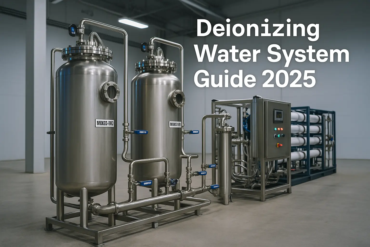
1) Where a deionizing water system fits in the process train
Typical lines place a deionizing water system after RO to polish residual ions before storage/distribution. Common sequences:
- RO → Two-bed DI (cation + anion) → Mixed bed polish → Storage & loop
- RO → EDI → (Optional) Mixed bed cartridge polish → Storage & loop
- When hygiene matters, use stainless-steel tanks, valves and housings with sanitary slopes, no dead legs, and validated rinsing.
Related guides: EDI vs mixed bed ion exchange - UF pretreatment (particle & bioload control)
Well-designed deionizing water systems stabilize downstream loops and reduce polishing media consumption.

2) Working principle of a deionizing water system (resins & chemistry)
DI relies on ion-exchange resins to replace dissolved ions with H+ and OH−, forming H2O. Implementations:
- Two-bed DI: cation resin (SAC, H+ form) then anion resin (SBA, OH− form). Robust, easy to regenerate onsite.
- Mixed bed DI: intimate mix of cation/anion beads in one vessel, delivering the lowest conductivity; often used as final polish or in cartridges.
- Service DI: vendor swaps pre-regenerated tanks—no onsite chemicals; higher cost per m3 but fast and compliant.
Resin types that matter
- SAC (strong-acid cation): tolerant, handles Ca/Mg/Na; regenerated by HCl or H2SO4.
- SBA (strong-base anion): Type I vs Type II—Type I excels at silica/nitrate; Type II offers better efficiency at warm temps but weaker on silica.
- WBA (weak-base anion): removes mineral acids but not silica/CO2; used as an efficiency stage upstream of SBA.
Silica & CO2 control
Silica and CO2 decide your anion loading and final quality. Lower them by RO pH control, degassing, or interstage alkalinity conditioning. High CO2 inflates conductivity yet “passes through” RO—plan for it.
3) Feed requirements & pretreatment before DI
- Oxidants: remove free chlorine/chloramine ahead of RO/DI (GAC or SBS). Oxidants attack polyamide and some resins.
- Particles & bio: multimedia/U F + biocontrol; target SDI < 3 to protect RO & DI.
- Organics: GAC or UV-TOC as required by spec; organics foul anion resin and raise TOC in product.
- CO2 & degassing: vacuum or membrane degas at interstage to cut anion load and stabilize conductivity.
When blending RO feed or designing antiscalant upstream, use our LSI calculator.
4) Sizing a deionizing water system—method, formulas & worked examples
4.1 Design steps (quick)
- Collect RO permeate analysis: conductivity (µS/cm), alkalinity/CO2, silica, temperature, and daily volume profile.
- Convert ionic load to mg/L as CaCO3 (order-of-magnitude: 2 µS/cm ≈ 1 mg/L as CaCO3 for low-TDS waters).
- Pick service time (e.g., 8–24 h) between regenerations/swaps and apply a quality safety margin (breakthrough at 50–70% of spec).
- Size resin volume from capacity per cycle & load; check hydraulic limits (Bv/h) and ΔP.
4.2 Typical capacities (industrial ranges)
| Resin | Practical capacity/cycle | Opmerkingen |
|---|---|---|
| SAC (H+) | 1.25–1.9 eq/L (≈20–30 kgr/ft³) | Depends on acid type & rinse; HCl more common. |
| SBA (OH−) | 0.95–1.6 eq/L (≈15–25 kgr/ft³) | Silica/CO2 reduce effective capacity. |
| Mixed bed | Polish to sub-µS/cm | Size by run time & target ΔP; used near spec limits. |
4.3 Worked example A — 2.0 m³/h polish to < 5 µS/cm
Given: RO permeate 20 µS/cm (~10 mg/L as CaCO3), 16 h/day, target mixed bed polish.
- Daily equivalents ≈ (10 mg/L × 2.0 × 16,000 L)/50,000 mg/eq ≈ 6.4 eq/day.
- Two-bed DI: choose 2 × 50 L per vessel (duty/standby). Using 1.5 eq/L capacity → 75 eq per vessel—ample margin for weekly regen.
- Add 10 L mixed bed cartridge skid as final deionizing water system polish; trigger swap at 70% of spec.
4.4 Hydraulics & ΔP checks
- Bed velocity: 5–40 Bv/h (industrial DI); keep pressure drop < 0.7–1.0 bar per vessel at design flow.
- Rinse volumes: allow 2–5 bed volumes for displacement & rinse-to-spec after regeneration.
- For sanitary systems use 316L vessels, orbital welds, and low-shedding elastomers; see our stainless-steel portfolio.
5) Regeneration & waste handling (onsite DI)
5.1 Chemistry selections
- Cation (SAC): HCl 4–8% or H2SO4 2–4% (watch CaSO4 scaling at higher strengths).
- Anion (SBA): NaOH 4–6% for Type I/II; warm caustic improves organics removal.
- Flow modes: co-current (simpler) vs counter-current (higher efficiency, lower leakage).
5.2 Neutralization & safety
- Segregate acid/caustic drains; neutralize to pH 6–9 with adequate residence and monitoring.
- Full PPE, eyewash/ shower, interlocks for chemical transfer; follow OEM SOPs and local permits.

6) Configuration choices—two-bed DI, mixed bed, service DI, and EDI hybrid
| Configuration | Quality | Capex/Opex | When to pick |
|---|---|---|---|
| Two-bed DI | 1–10 µS/cm | Low OPEX at volume; capex for regen | Steady plants with utilities and staff |
| Mixed bed DI | < 1 µS/cm | Medium; frequent polish media swaps | Final polish or variable tools |
| Service DI | Vendor-guaranteed | High per m³; zero chemicals onsite | GMP/labs/startups & tight HSE |
| EDI hybrid | Sub-µS/cm continuous | Stable OPEX; no bulk chemicals | Stable RO, chemical restrictions |
Deep dive: EDI vs mixed bed—selection guide.
7) Instrumentation, control & acceptance criteria
- Inline meters: feed/product conductivity, temperature, ΔP; optional TOC & silica monitors for high-purity loops.
- Exhaustion control: conductivity breakpoints with delay/confirm timers; auto divert until rinse-to-spec.
- Trending: day-to-day conductivity @ set load, ΔP, resin run-hours; investigate step changes immediately.
- Typical acceptance (indicative—use contract specs): product ≤ target µS/cm at 25 °C; silica within limit; TOC where applicable.
8) OPEX—what drives the cost of a deionizing water system
- Chemicals: acid/caustic per regeneration and rinse loss.
- Media: resin life (oxidants/organics, iron fouling) & mixed-bed cartridge frequency.
- Nutsvoorzieningen: pump kWh/m³, neutralization, wastewater fees.
- Labor & service: in-house operators vs service-DI logistics.
For RO front-end cost modeling, see our RO OPEX calculator.
Right pretreatment upstream of a deionizing water system is the single biggest lever to cut OPEX.
9) Commissioning SOP—for DI skids and loops
- Verify materials & cleanliness (316L, elastomers, seals); flush to clear particles; check leak-tightness.
- Load/stratify resins correctly (for mixed bed, follow OEM separation/air scour procedures).
- Cold rinse, then chemical regeneration (onsite DI), then rinse-to-spec with inline conductivity sampling.
- Baseline recording: feed/product conductivity vs flow/temp; document release criteria and sampling plan.
10) Troubleshooting map—fast triage
| Symptom | Likely root causes | First checks |
|---|---|---|
| Product conductivity rising | Resin exhaustion, CO2 spike, silica breakthrough, flow beyond design | Trend vs temperature; check degas/alkalinity; verify regeneration and divert timings |
| ΔP high | Fines/particulates, channeling collapse, biofouling | Sample bed/fines, review pretreatment & filter changes, backwash/air scours (where allowed) |
| TOC out of spec | Organics leakage from anion resin or upstream GAC saturation | Warm caustic clean, GAC service, UV-TOC check, replace polish cartridge |
11) FAQ—deionizing water system
How low can conductivity go?
Two-bed DI typically reaches 1–10 µS/cm; a mixed bed or EDI polish can reach sub-µS/cm if RO feed is conditioned (low CO2, stable temperature).
Onsite DI vs service DI?
Onsite DI wins at large steady volumes; service DI eliminates chemicals and speeds compliance at a higher per-m³ cost.
How do I handle silica?
Prefer SBA Type I, maintain temperature control, consider degassing/pH conditioning interstage, and add a mixed-bed polish when specs are tight.
Next steps
Share your RO permeate analysis and demand curve — we’ll size your deionizing water system (resin volumes, vessel diameters, regeneration strategy) and propose a hygienic stainless-steel tank & distribution package.
Een offerte aanvragen - Stainless-steel tanks & housings - EDI vs mixed bed
Author & Review: Stark Water process team (10+ years in RO/DI/EDI projects). Last reviewed: 2025-10-20.
Further reading: ASTM D1193 - WQA resources